
What Is a Polarization Modulator and How Does It Work?
A Polarization Modulator controls the orientation or ellipticity of light’s electric field. It can switch between horizontal and vertical polarization, rotate a linear state, or create circular polarization. The change may be subtle to the eye. Yet a sensor, optical link, or laboratory instrument can detect it.
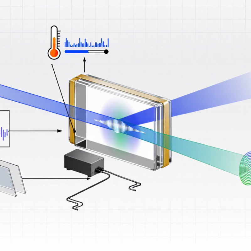
In many designs, an electric field changes the refractive properties of an electro-optic crystal. This shifts the phase between two perpendicular components of the light wave. The resulting polarization depends on the input state, applied voltage, crystal properties, and optical alignment. Photonics author Dr. Rüdiger Paschotta’s technical explanations of electro-optic modulators describe this core principle: an applied field can alter a material’s optical properties and thereby control light. That is a paraphrase, not a verbatim quotation.
The hardware may include a crystal, electrodes, a voltage driver, and carefully aligned optics. Some devices use other mechanisms, so the label alone does not reveal their full design. That distinction matters. A setup that works at one wavelength may perform differently at another; temperature, insertion loss, and bandwidth also shape the result. A tilted mount or unstable voltage can introduce unwanted polarization changes. Small errors show. Understanding how a Polarization Modulator works therefore means following both the light’s path and the conditions that influence it. This guide introduces the operating principle, common designs, and practical factors engineers check when selecting or testing a device. Some details remain application-specific. That is worth remembering.
Definition and Purpose of a Polarization Modulator
A polarization modulator is an optical device that deliberately changes the polarization state of light. It may alter the angle of linear polarization, or convert light into an elliptical or circular state. Its purpose is to give researchers and engineers controlled access to these changes, rather than relying on fixed optical components.
In a common arrangement, linearly polarized light passes through an electro-optic crystal. A voltage changes the crystal’s optical properties, creating a phase delay between perpendicular components of the beam. The resulting polarization depends on the voltage, crystal orientation, and incoming light. The device does not always “rotate” light in the simple sense. That distinction matters. In a laboratory, an analyzer placed after the modulator can reveal the change as a shifting brightness pattern. Modulators support tasks such as optical measurement, imaging, and signal control. They can also help test how materials affect polarized light.
The label covers devices with different designs and operating limits. Speed, wavelength range, and temperature sensitivity can all affect performance. A setup that works cleanly on an optical bench may need careful alignment in a practical instrument. That detail is easy to underestimate. The basic definition is useful, but it does not capture every trade-off.
How Polarization States of Light Are Described
A polarization state describes the direction and changing pattern of light’s electric field. Imagine a beam traveling toward a sensor: its field may trace a straight line, a circle, or an ellipse. For fully polarized light, a Jones vector represents two perpendicular field components, often labeled horizontal and vertical. Their amplitudes show relative strength; their phase difference shows how they move relative to each other. That phase matters. Equal components with no phase offset produce diagonal linear polarization, while a quarter-cycle offset can produce circular polarization.
The Stokes parameters offer another description, especially when light is partly polarized or mixed. They summarize total intensity and the balance of linear and circular polarization, rather than tracking the field’s phase directly. A polarimeter can estimate these values from measurements through different analyzer orientations. In practice, imperfect optics and detector noise can blur the textbook categories. Light may be mostly, not perfectly, circular. A polarization modulator changes the relative phase or amplitude of field components, shifting the state in a controlled way. Seeing that change on a polarization plot makes the abstract description more tangible: a point moves across the sphere as the light’s state changes.
| Topic | Description or Example | What It Tells You |
|---|---|---|
| Electric-field components | For light traveling along the z-axis, the transverse electric field can be represented by components Ex and Ey. | Their relative amplitudes and phase determine the polarization state. |
| Jones vector | A fully polarized field is represented by a two-component complex vector, such as (Ex, Ey)T. | It describes the amplitudes and relative phase of the two orthogonal field components. |
| Horizontal linear polarization | Normalized Jones vector: (1, 0)T Normalized Stokes vector: (1, 1, 0, 0) | The electric field oscillates along the x-axis. |
| Vertical linear polarization | Normalized Jones vector: (0, 1)T Normalized Stokes vector: (1, −1, 0, 0) | The electric field oscillates along the y-axis. |
| Linear polarization at +45° | Normalized Jones vector: (1, 1)T/√2 Normalized Stokes vector: (1, 0, 1, 0) | The x and y components have equal amplitudes and are in phase. |
| Linear polarization at −45° | Normalized Jones vector: (1, −1)T/√2 Normalized Stokes vector: (1, 0, −1, 0) | The x and y components have equal amplitudes and opposite signs. |
| Circular polarization | Example Jones vector: (1, i)T/√2 Normalized Stokes vector under the convention below: (1, 0, 0, 1) | The orthogonal components have equal amplitudes and a phase difference of 90°. The handedness name depends on the convention used. |
| Stokes parameters | S0 is total intensity; S1 compares horizontal and vertical components; S2 describes the ±45° balance; S3 describes circular polarization. | The Stokes vector (S0, S1, S2, S3) can describe fully or partially polarized light. |
| Polarization modulator | An optical device that changes a light beam’s polarization, often by controlling the phase difference between orthogonal field components. | Changing the relative phase can convert, for example, linear polarization into elliptical or circular polarization. |
| Electro-optic modulation | An applied electric field can change a material’s refractive indices through the electro-optic effect, altering the phase delay between polarization components. | The polarization can be varied electrically, with the result depending on the material, device geometry, and applied voltage. |
| Retardance | The phase delay between two orthogonal components. A quarter-wave retardance is π/2 radians; a half-wave retardance is π radians. | With a suitable input polarization and device orientation, these phase delays can produce circular or rotated linear polarization, respectively. |
| Convention note | The normalized Stokes values use S1 = |Ex|² − |Ey|², S2 = 2 Re(Ex*Ey), and S3 = 2 Im(Ex*Ey). Circular-polarization handedness labels and the sign assigned to S3 can differ between conventions. | |
Key Components and Modulation Mechanisms
A polarization modulator controls light’s polarization state, not merely its brightness. Its key components are a polarization-conditioned input, an electro-optic medium, drive electrodes, and an output path. Lithium niobate is commonly used because an applied electric field changes its refractive indices. Think of two perpendicular light components traveling through a small crystal block while voltage shifts their relative phase.
That phase shift changes the output from linear polarization toward elliptical or circular polarization. A downstream analyzer can convert the change into an intensity signal, while some systems measure polarization directly. The textbook picture is clean; real alignment is less forgiving. ITU’s Facts and Figures 2023 reported 5.4 billion people online, about 67% of the global population. That scale helps explain the need for precise optical control in communications, though it does not measure modulator demand itself.
Tips: Check the input polarization and electrode drive before judging performance. A slight alignment error can look like weak modulation. Keep the optical path stable, and record voltage alongside output readings. Small details matter.
Common Types of Polarization Modulators
Polarization modulators control light’s orientation or the phase difference between two perpendicular polarization components. Electro-optic types use an applied voltage to change a crystal’s refractive index. They respond quickly, making them useful in high-speed optical links and laboratory systems. Liquid-crystal modulators reorient molecules to adjust polarization. They often need less drive power, but their response is slower. Fiber-based squeezers apply mechanical stress to a fiber, changing its birefringence. They are compact, though temperature and vibration can affect their settings.
The right type depends on speed, stability, and optical loss. No type wins everywhere. The Optical Internetworking Forum’s 400ZR Implementation Agreement specifies dual-polarization 16-QAM operation near 60 gigabaud in coherent links. This shows why precise polarization control matters: both polarization channels carry data. It does not mean every modulator suits that application. In practice, engineers also check wavelength range, insertion loss, and how well the device maintains its setting. That last detail is easy to underestimate.
Tips: For a bench test, rotate the input polarization and record output power at each setting. Repeat after the device warms up. Small changes can reveal drift that a single reading misses.
What Is a Polarization Modulator and How Does It Work?
Common types change the phase or orientation of polarized light in response to an applied control signal.
The curves are idealized and normalized, not measured device data. Electro-optic retardance and Faraday rotation are shown as proportional to their respective control fields; liquid-crystal retardance is shown as a nonlinear, saturating response. Actual behavior depends on device design and operating conditions.
Applications and Factors Affecting Performance
Polarization modulators are useful when an optical system needs to control how light is oriented, not merely how bright it is. In fiber communication, they can help encode or manage polarization states. In sensing and interferometry, controlled changes reveal small shifts caused by stress, motion, or material properties. Microscopy systems may also use them to adjust contrast or probe samples. The right application depends on how quickly the polarization must change and how much optical loss the setup can tolerate.
Performance depends on wavelength, drive voltage, modulation speed, and the modulator’s extinction ratio. A device optimized for one wavelength may perform less well at another. Temperature can shift its response, while imperfect alignment may introduce unwanted loss or polarization errors. Timing matters. In a lab, a tiny alignment change can show up as a measurable signal difference. Small shifts count.
Practical testing should include the full optical path, not just the modulator on its own. Connect the intended light source, detector, and control electronics, then measure insertion loss and polarization contrast under operating conditions. In practice, the neat laboratory picture can be misleading: cables, mounts, and temperature changes all affect stability. It is tempting to treat specifications as guarantees, but real setups often need careful adjustment. That part is easy to underestimate.